Other Parts of This Series:
- Part 2: Software Design Patterns and Principles - Part 2 (Classification and Most Used Design Patterns)
- Part 4: Software Design Patterns and Principles - Part 4 (Singleton Design Pattern)
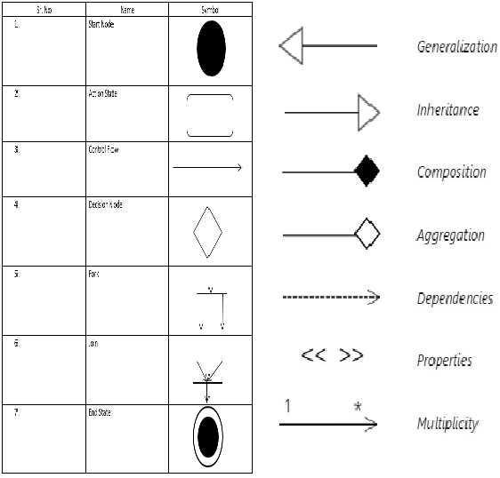
UML Signs (Photo Credit: SmartDraw + EDUCBA)
In this series, we try to explore software design patterns and principles. We will try to learn the well-known OOP design patterns one by one. In this part, we try to understand the UML and relations between objects, so that we can easily grab the future parts.
So let’s get started…
Story
Once upon a time in Dreamland, Somrat and Habiba met each other. They talked and became known to each other. Gradually a relationship was built between them. Their relationship could be described in 3 phases. Like:
- Phase 1: First they just become known to each other and become just friends.
- Phase 2: They became more than just friends and married each other.
- Phase 3: Their relationship becomes stronger than ever, and they promise to die together.
UML Basics
UML stands on Unified Modeling Language. It is a standardized modeling language used to visualize, specify, construct, and document the components of a software system.
The current UML standards call for 13 different types of diagrams and are organized into two distinct groups:
1. Structural Diagrams
- Class diagram: Describes classes, attributes, methods, and relationships between them.
- Package diagram: Organizes classes or components into packages to show dependencies.
- Object diagram: Shows instances (objects) of classes and their relationships at a specific time.
- Component diagram: Represents the organization and dependencies among software components.
- Composite structure diagram: Describes the internal structure of a class and collaborations among its parts.
- Deployment diagram: Depicts the physical deployment of artifacts on hardware nodes.
2. Behavioral or Interaction Diagrams
- Activity diagram: Models the workflow or business process as a sequence of actions.
- Sequence diagram: Shows object interactions in a time-ordered sequence of messages.
- Use case diagram: Illustrates system functionality and interactions between actors and use cases.
- State diagram: Represents states of an object and transitions triggered by events.
- Communication diagram: Displays object interactions and message flows focusing on relationships.
- Interaction overview diagram: Combines activity and sequence diagrams to show control flow among interactions.
- Timing diagram: Shows object states or conditions over time, emphasizing timing constraints.
To Know More About UML Notations Please check out this link.
Relations Between Objects
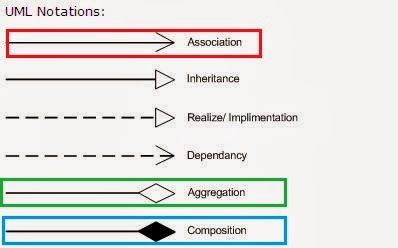
UML Notation (Photo Credit: javarevisited)
In OOP, we build software by establishing the connection and different types of relations between different objects. These relations can be expressed by different terms. Like:
Association:
More simply, association refers to the fact that an object has or is in a relationship with another object. It means an object is associated with another object, or both objects are known to each other.
- Represents a “uses” or “has-a” relationship.
- It’s a structural link between two classes.
- Represented by a solid line connecting classes.
In the above story, Somrat and Habiba are two objects, and they are associated or have a relationship.
Aggregation:
Aggregation is a phase or type of association. In that form of association, relationships between 2 objects become stronger than normal association relations. In that form of association, both objects are owned by themselves, and one object never kills or destroys another.
- Represents a “whole-part” relationship, but the part can exist independently of the whole.
- Denoted by a hollow diamond at the “whole” end.
In the above story, phase 2 can be considered an aggregation relationship. Here both Somrat and Habiba create a better relationship by getting married, but if one dies, the other does not necessarily die too.
Composition:
Composition is the stronger relationship form of association and aggregation. In that form of relationship an object owns another object, and when this object dies, it also kills or other objects also die with it. That means the primary object is responsible for other objects’ lifetimes.
- A stronger form of aggregation.
- The part cannot exist without the whole.
- Denoted by a filled diamond at the “whole” end.
In the above story, phase 3 can be considered a composition relationship between Somrat and Habiba. They are promised to die together and live together. It means one object is responsible for another object.
Generalization / Inheritance:
- Represents an “is-a” relationship.
- Denoted by a solid line with a hollow triangle pointing to the parent.
Dependency:
- Represents a “uses” or “depends on” relationship.
- Denoted by a dashed arrow from the dependent class to the independent one.
In the above picture, you can find the UML notation for association, aggregation, and composition.